- Proprietary Cisco Layer 2 protocol that uses multicast to gather hardware and protocol information about directly connected devices.
- Network layer protocol and media independent.
- Enabled by default on all Cisco devices, but can be disabled globally:
Router(config)#nocdp run
or can be disabled on interface-by-interface basis:
Router(config-if)#nocdp enable
- To learn the remote device’s Layer 3 address and IOS version
Router>showcdp neighbor detail
or
Router>showcdp entry *
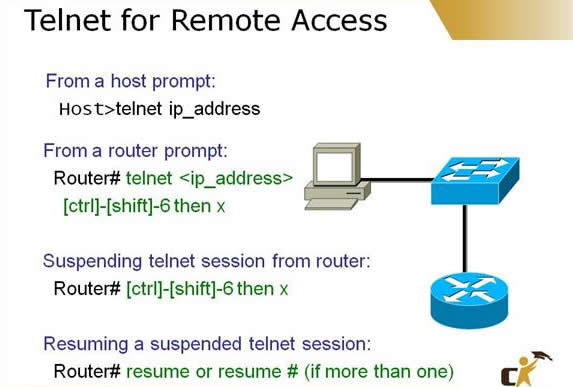
Telnet
Telnet enables a virtual terminal connection to a remote device’s IP address using the Application layer protocol called Telnet (TCP port 23 at the Transport layer).
To Telnet from IOS, enter the keywordtelnetfollowed by the IP address or hostname. If youenter only an IP address or hostname in user or privileged EXEC, IOS automatically assumes that you are Telnetting. To Telnet to a Cisco device, the vty passwords must be set, or you receive the “Password required, but none set” error. To access Privileged EXEC in a Telnet session, you must have enable password set, or you receive the “% No password set” error.
- To suspend the Telnet session, press Ctrl+Shift+6, x.
- To see a list of the active sessions in the originating router, use the show sessions command.
- To resume a suspended session, press the Enter key from user EXEC or privileged EXEC mode, or enter resume followed by the session number.
- To close a Telnet session from the device you are Telnetted into, enter exitor logout from user EXEC or privileged EXEC mode.
- To close a Telnet session from the originating device, enter disconnect followed by the session number.
- To see log messages in your Telnet session, use the privileged EXEC mode command terminal monitor in the device that you are Telnetted into.
Your Cisco device can act as a DHCP server and respond to DHCP requests on a segment. To configure the Cisco device as a DHCP server, you must first enable the interface that will receivethe DHCP requests and assign an IP address to it. After the interface is enabled, you define theDHCP address pool with theip dhcp pool poolname global configuration command. Indhcp – configmode, you can define the DHCP address scope with thenetwork command followed bythe IP subnet to be assigned. You can also define additional parameters such as the default gate-way, DNS server, domain name, and length of the IP lease. To exclude IP addresses from being assigned (such as if you have statically assigned them to specific devices), use the ip dhcp excluded -address ip-addresscommand to remove the IP(s) from the scope.
To verify the devices that have been assigned IP addresses from the DHCP address scope, use the show dhcp bindings command.
Switches
Switches have the following functions:
- Segment LANs into multiple collision domains.
- Learn MAC addresses by examining the source MAC address of each frame received and store them in a CAM table.
- Base their forwarding decisions based on the destination MAC address of an Ethernet frame.
- Flood broadcast, multicast, and unknown unicast frames out all ports except the one it was received.
A switch has three methods of forwarding frames:
Store-and-forward: Latency varying transmission method that buffers the entire frame and calculates the CRC before forwarding the frame.
Cut-through: Only looks at the destination MAC address in an Ethernet frame and forwards it.
Fragment-free: Checks the first 64 bytes for frame fragments (due to collisions) before forwarding the fame.
Duplex Connections
- Half-duplex interfaces have one-way communication with suboptimal throughput because they operate in a collision domain in which CSMA/CD must be enabled. When connected to a hub, they must run half duplex.
- Full-duplex interfaces simultaneously send and receive, allowing higher throughput because CSMA/CD is disabled. Connections to other switches or devices can be full duplex.
Spanning Tree Protocol IEEE 802.1d
STP is a Layer 2 protocol that is used to prevent switching loops in networks with redundant switched paths.
| TABLE | STP Port States | |
| State | Function | Transition Time |
| Disabled | The interface is administratively shut downor disabled from port violation. | NA |
| Blocking | Does not forward any user data. All ports start out in this state.Does not send, but still can receive BPDUs to react to topology changes. | 0 to 20 seconds |
| ListeningLearning | Begins to transition to a forwarding state by listening and sending BPDUs.No user data sent.Begins to build MAC addresses learned on the interface. No user data sent. | 15 seconds15 seconds |
| Forwarding | User data forwarded. |
STP elects root bridge/switch by determining which switch has the lowest Bridge ID in the topology learned from sending and receiving BPDUs. Bridge ID is a combination of Priority and MAC address.
All nonroot switches determine root port based on the fastest (lowest cumulative cost) path back to root switch. If a tie occurs, the Bridge ID followed by port priority and port number are the tie breakers.
On each segment, the switch advertising the fastest way back to the root switch is the designated port for that segment.
If port is not a root or a designated port, it is blocking.
| Port Cost Values | |
| Interface | Cost |
| 10Gbps | 2 |
| 1Gbps | 4 |
| 100Mbps | 19 |
| 10Mbps | 100 |
Your purchase with Ciscoforall is safe and fast.
Your Learning Solution will be available for immediate download after your payment has been received.
 |  |