Frame Relay is a standardized wide area network technology that specifies the physical and logical link layers of digital telecommunications channels using a packet switching methodology. Originally designed for transport across Integrated Services Digital Network (ISDN) infrastructure, it may be used today in the context of many other network interfaces.
Network providers commonly implement Frame Relay for voice (VoFR) and data as an encapsulation technique, used between local area networks (LANs) over a wide area network (WAN). Each end-user gets a private line (or leased line) to a Frame Relay node. The Frame Relay network handles the transmission over a frequently-changing path transparent to all end-users.
Frame Relay has become one of the most extensively-used WAN protocols. Its cheapness (compared to leased lines) provided one reason for its popularity. The extreme simplicity of configuring user equipment in a Frame Relay network offers another reason for Frame Relay’s popularity.
With the advent of Ethernet over fiber optics, MPLS, VPN and dedicated broadband services such as cable modem and DSL, the end may loom for the Frame Relay protocol and encapsulation.[citation needed] However many rural areas remain lacking DSL and cable modem services. In such cases the least expensive type of non-dial-up connection remains a 64-kbit/s frame-relay line. Thus a retail chain, for instance, may use Frame Relay for connecting rural stores into their corporate WAN.

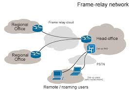
A basic Frame Relay network
The designers of Frame Relay aimed to a telecommunication service for cost-efficient data transmission for intermittent traffic between local area networks (LANs) and between end-points in a wide area network (WAN). Frame Relay puts data in variable-size units called “frames” and leaves any necessary error-correction (such as re-transmission of data) up to the end-points. This speeds up overall data transmission. For most services, the network provides a permanent virtual circuit (PVC), which means that the customer sees a continuous, dedicated connection without having to pay for a full-time leased line, while the service-provider figures out the route each frame travels to its destination and can charge based on usage.
An enterprise can select a level of service quality – prioritizing some frames and making others less important. Frame Relay can run on fractional T-1 or full T-carrier system carriers. Frame Relay complements and provides a mid-range service between basic rate ISDN, which offers bandwidth at 128 kbit/s, and Asynchronous Transfer Mode (ATM), which operates in somewhat similar fashion to frame Relay but at speeds from 155.520 Mbit/s to 622.080 Mbit/s.
Frame Relay has its technical base in the older X.25 packet-switching technology, designed for transmitting data on analog voice lines. Unlike X.25, whose designers expected analog signals, Frame Relay offers a fast packet technology, which means that the protocol does not attempt to correct errors. When a Frame Relay network detects an error in a frame, it simply drops that frame. The end points have the responsibility for detecting and retransmitting dropped frames. (However, digital networks offer an incidence of error extraordinarily small relative to that of analog networks.)
Frame Relay often serves to connect local area networks (LANs) with major backbones as well as on public wide-area networks (WANs) and also in private network environments with leased lines over T-1 lines. It requires a dedicated connection during the transmission period. Frame Relay does not provide an ideal path for voice or video transmission, both of which require a steady flow of transmissions. However, under certain circumstances, voice and video transmission do use Frame Relay.
Frame Relay originated as an extension of Integrated Services Digital Network (ISDN). Its designers aimed to enable a packet-switched network to transport the circuit-switched technology. The technology has become a stand-alone and cost-effective means of creating a WAN.
Frame Relay switches create virtual circuits to connect remote LANs to a WAN. The Frame Relay network exists between a LAN border device, usually a router, and the carrier switch. The technology used by the carrier to transport data between the switches is variable and may differ among carriers (i.e. to function, a practical Frame Relay implementation need not rely solely on its own transportation mechanism).
The sophistication of the technology requires a thorough understanding of the terms used to describe how Frame Relay works. Without a firm understanding of Frame Relay, it is difficult to troubleshoot its performance.
Frame-relay frame structure essentially mirrors almost exactly that defined for LAP-D. Traffic analysis can distinguish Frame Relay format from LAP-D by its lack of a control field.
Protocol data unit
Each Frame Relay Protocol data unit (PDU) consists of the following fields:
- Flag Field. The flag is used to perform high-level data link synchronization which indicates the beginning and end of the frame with the unique pattern 01111110. To ensure that the 01111110 pattern does not appear somewhere inside the frame, bit stuffing and destuffing procedures are used.
- Address Field. Each address field may occupy either octet 2 to 3, octet 2 to 4, or octet 2 to 5, depending on the range of the address in use. A two-octet address field comprises the EA=ADDRESS FIELD EXTENSION BITS and the C/R=COMMAND/RESPONSE BIT.
- DLCI-Data Link Connection Identifier Bits. The DLCI serves to identify the virtual connection so that the receiving end knows which information connection a frame belongs to. Note that this DLCI has only local significance. A single physical channel can multiplex several different virtual connections.
- FECN, BECN, DE bits. These bits report congestion:
- FECN=Forward Explicit Congestion Notification bit
- BECN=Backward Explicit Congestion Notification bit
- DE=Discard Eligibility bit
- Information Field. A system parameter defines the maximum number of data bytes that a host can pack into a frame. Hosts may negotiate the actual maximum frame length at call set-up time. The standard specifies the maximum information field size (supportable by any network) as at least 262 octets. Since end-to-end protocols typically operate on the basis of larger information units, Frame Relay recommends that the network support the maximum value of at least 1600 octets in order to avoid the need for segmentation and reassembling by end-users.
- Frame Check Sequence (FCS) Field. Since one cannot completely ignore the bit error-rate of the medium, each switching node needs to implement error detection to avoid wasting bandwidth due to the transmission of erred frames. The error detection mechanism used in Frame Relay uses the cyclic redundancy check (CRC) as its basis.
Frame Relay origins
Frame Relay began as a stripped-down version of the X.25 protocol, releasing itself from the error-correcting burden most commonly associated with X.25. When Frame Relay detects an error, it simply drops the offending packet. Frame Relay uses the concept of shared-access and relies on a technique referred to as “best-effort”, whereby error-correction practically does not exist and practically no guarantee of reliable data delivery occurs. Frame Relay provides an industry-standard encapsulation utilizing the strengths of high-speed, packet-switched technology able to service multiple virtual circuits and protocols between connected devices, such as two routers.
Frame Relay versus X.25
| The OSI Model | |
|---|---|
| 7 | Application Layer |
| 6 | Presentation Layer |
| 5 | Session Layer |
| 4 | Transport Layer |
| 3 | Network Layer |
| 2 | Data Link Layer
|
| 1 | Physical Layer |
| This box: view · talk · edit | |
X.25 provides quality of service and error-free delivery, whereas, Frame Relay was designed to relay data as quickly as possible over low error networks. Frame Relay eliminates a number of the higher-level procedures and fields used in X.25. Frame Relay was designed for use on links with error-rates far lower than available when X.25 was designed.
X.25 prepares and sends packets, while Frame Relay prepares and sends frames. X.25 packets contain several fields used for error checking and flow control, most of which are not used by Frame Relay. The frames in Frame Relay contain an expanded link layer address field that enables Frame Relay nodes to direct frames to their destinations with minimal processing. The elimination of functions and fields over X.25 allows Frame Relay to move data more quickly, but leaves more room for errors and larger delays should data need to be retransmitted.
X.25 packet switched networks typically allocated a fixed bandwidth through the network for each X.25 access, regardless of the current load. This resource allocation approach, while apt for applications that require guaranteed quality of service, is inefficient for applications that are highly dynamic in their load characteristics or which would benefit from a more dynamic resource allocation. Frame Relay networks can dynamically allocate bandwidth at both the physical and logical channel level.
Virtual circuits
As a WAN protocol, Frame Relay is most commonly implemented at Layer 2 (data link layer) of the Open Systems Interconnection (OSI) seven layer model. Two types of circuits exist: permanent virtual circuits (PVCs) which are used to form logical end-to-end links mapped over a physical network, and switched virtual circuits (SVCs). The latter are analogous to the circuit-switching concepts of the public switched telephone network (PSTN), the global phone network.
Frame Relay origins
Frame Relay began as a stripped-down version of the X.25 protocol, releasing itself from the error-correcting burden most commonly associated with X.25. When Frame Relay detects an error, it simply drops the offending packet. Frame Relay uses the concept of shared-access and relies on a technique referred to as “best-effort”, whereby error-correction practically does not exist and practically no guarantee of reliable data delivery occurs. Frame Relay provides an industry-standard encapsulation utilizing the strengths of high-speed, packet-switched technology able to service multiple virtual circuits and protocols between connected devices, such as two routers.
Local Management Interface (LMI)
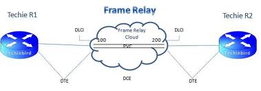
Datalink connection identifiers (DLCIs) are numbers that refer to paths through the Frame Relay network. They are only locally significant, which means that when device-A sends data to device-B it will most-likely use a different DLCI than device-B would use to reply. Multiple virtual circuits can be active on the same physical end-points (performed by using subinterfaces).
The LMI global addressing extension gives Frame Relay data-link connection identifier (DLCI) values global rather than local significance. DLCI values become DTE addresses that are unique in the Frame Relay WAN. The global addressing extension adds functionality and manageability to Frame Relay internetworks. Individual network interfaces and the end nodes attached to them, for example, can be identified by using standard address-resolution and discovery techniques. In addition, the entire Frame Relay network appears to be a typical LAN to routers on its periphery.
LMI virtual circuit status messages provide communication and synchronization between Frame Relay DTE and DCE devices. These messages are used to periodically report on the status of PVCs, which prevents data from being sent into black holes (that is, over PVCs that no longer exist).
The LMI multicasting extension allows multicast groups to be assigned. Multicasting saves bandwidth by allowing routing updates and address-resolution messages to be sent only to specific groups of routers. The extension also transmits reports on the status of multicast groups in update messages.
Committed information rate (CIR)
Frame Relay connections are often given a committed information rate (CIR) and an allowance of burstable bandwidth known as the extended information rate (EIR). The provider guarantees that the connection will always support the CIR rate, and sometimes the EIR rate should there be adequate bandwidth. Frames that are sent in excess of the CIR are marked as discard eligible (DE) which means they can be dropped should congestion occur within the Frame Relay network. Frames sent in excess of the EIR are dropped immediately. All traffic exceeding the CIR is marked discard eligible.
Your purchase with Ciscoforall is safe and fast.
Your Learning Solution will be available for immediate download after your payment has been received.
 |  |